I have needed some form of air filtration in my garage workshop for quite a while. Every time I work on a project, there is a fine layer of dust covering everything within a day or so. There are commercial units available from companies such as Delta, ShopFox, Jet, Wen, and many more. There are also countless videos on YouTube from people that made their own. I took some inspiration from both the commercial and DIY versions. I can’t spare the floorspace needed for most of the DIY cart-style filters, so I had to look up for space.
I modeled the feature list of my design after commercial units by Jet and Wen:
- It needed to be remote controlled since it is ceiling mounted and out of reach.
- It should have multiple fan speeds - at least a high and low.
- It should have a timer for auto-off after a set time.
- It should have cheap, easily replaceable filter elements.
With that list of requirements, I turned to my old friend, the Arduino UNO microcontroller. I knew I could make it do what I wanted with a little patience and a lot of help from sites like stackexchange.
The electronic bits:
First I purchased all of the electronic components.
I already had the Arduino UNO on hand.
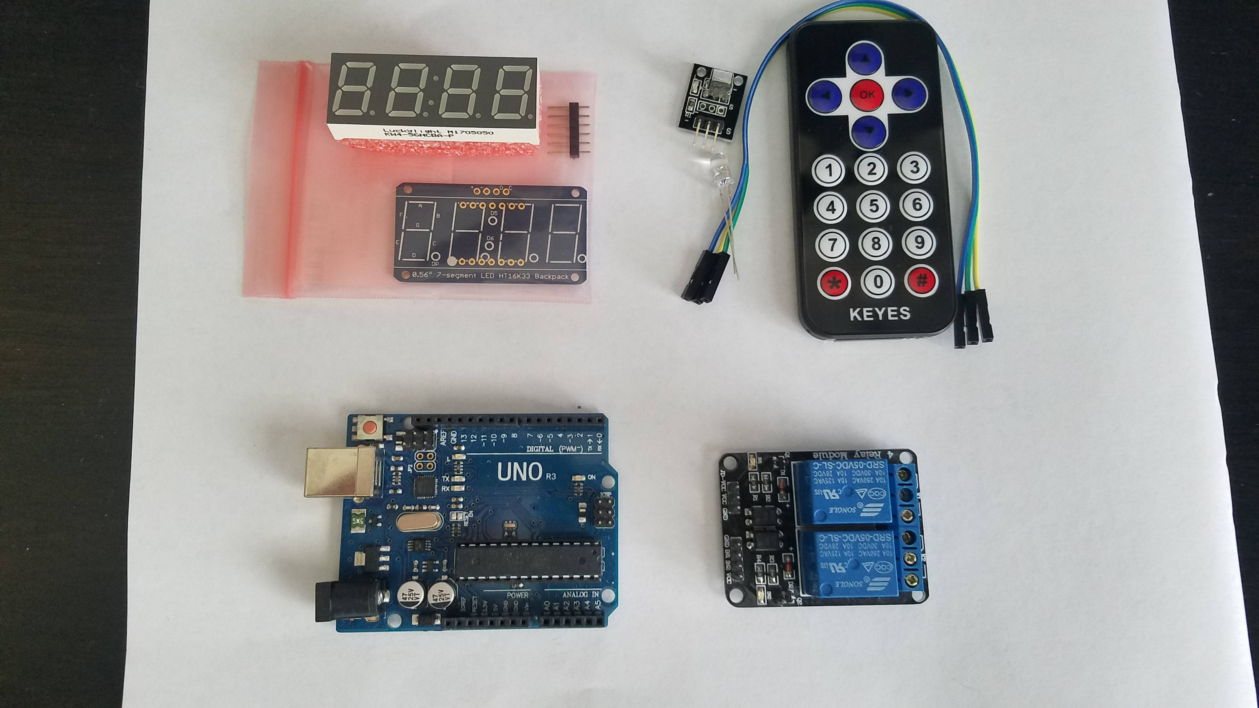
To control the AC power to the box fan motor, I bought a 2-channel relay module made by SainSmart. I have used these modules in the past, and knew they were a perfect fit for switching high voltage.
For the status display, I chose a 4-digit 7-segment I2C display from Adafruit. I really enjoy working with products from Adafruit. Their documentation, libraries, and example code is excellent. This was my first time interfacing a 7-segment display of any kind, but Adafruit’s examples made it very simple.
For the remote control, I bought a very cheap remote control module with receiver from ebay. The brand name on it is “KEYES”. There are many clones of this same device all over ebay, many with different names on them. I’m fairly sure almost any of them would work.
Finally, I used a generic arduino proto-shield that I already had on hand. Here is a link to a similar shield on Amazon.
Here is a picture of all the main parts I used, except for the proto-shield.
My approach to Arduino code development is to attack each of the new (unknown) hardware modules or functions, one at a time, and get each one working perfectly on its own. Lumping them all in together adds too many unknowns and can lead you down the wrong path to correction. I wired up the IR sensor, searched the web for examples of receiving and handling input as a starting point. That part was fairly easy. I mapped out the hex values for each of the remote buttons and then planned for the behavior of each button. Here is what I came up with:
- Left Arrow: Off from any state. Display shows “OFF” and then goes blank after a few seconds.
- Right Arrow: No function at this time
- Up Arrow: Change fan speed to HI if it was already running in any mode at LOW speed. Turn on the unit and set fan to HI speed if it was previously off.
- Down Arrow: Change fan speed to LOW if it was already running in any mode at HI speed. Turn on the unit and set fan to LOW speed if it was previously off.
- OK/Select: No function at this time
- 0 - 9 digits: Enter value for countdown timer - digits only register when in ‘time entry’ function.
- *(Star): Clear the countdown timer value - only registers when in ‘time entry’ function
- #: Start the countdown timer using the entered value
With that all settled, I wrote the code (lots and lots of case switching) to handle the IR remote inputs and deal with them differently, depending on what the device was doing prior to the new input. The hardest part of this section of code was dealing with the countdown timer - keeping it relatively accurate, while still watching for new inputs/interrupts from the remote. I worked through those problems over the course of a few days of on-and-off work on the project.
The next part of code was the 7-segment display. This was relatively simple thanks to the Adafruit libraries and examples. I had already worked out what I wanted the display to show at each stage of operation while I was writing the IR input portion of code. The hardest part of this task was figuring out the hexidecimal codes to send in order to form non-integer values on the display. For example, I wanted to show “HI”, LO", and “OFF” as the modes changed. I found a helpful resource online that got me through this part of the code.
I was so happy that I had finished the code, I posted a video of it operating on my desk.
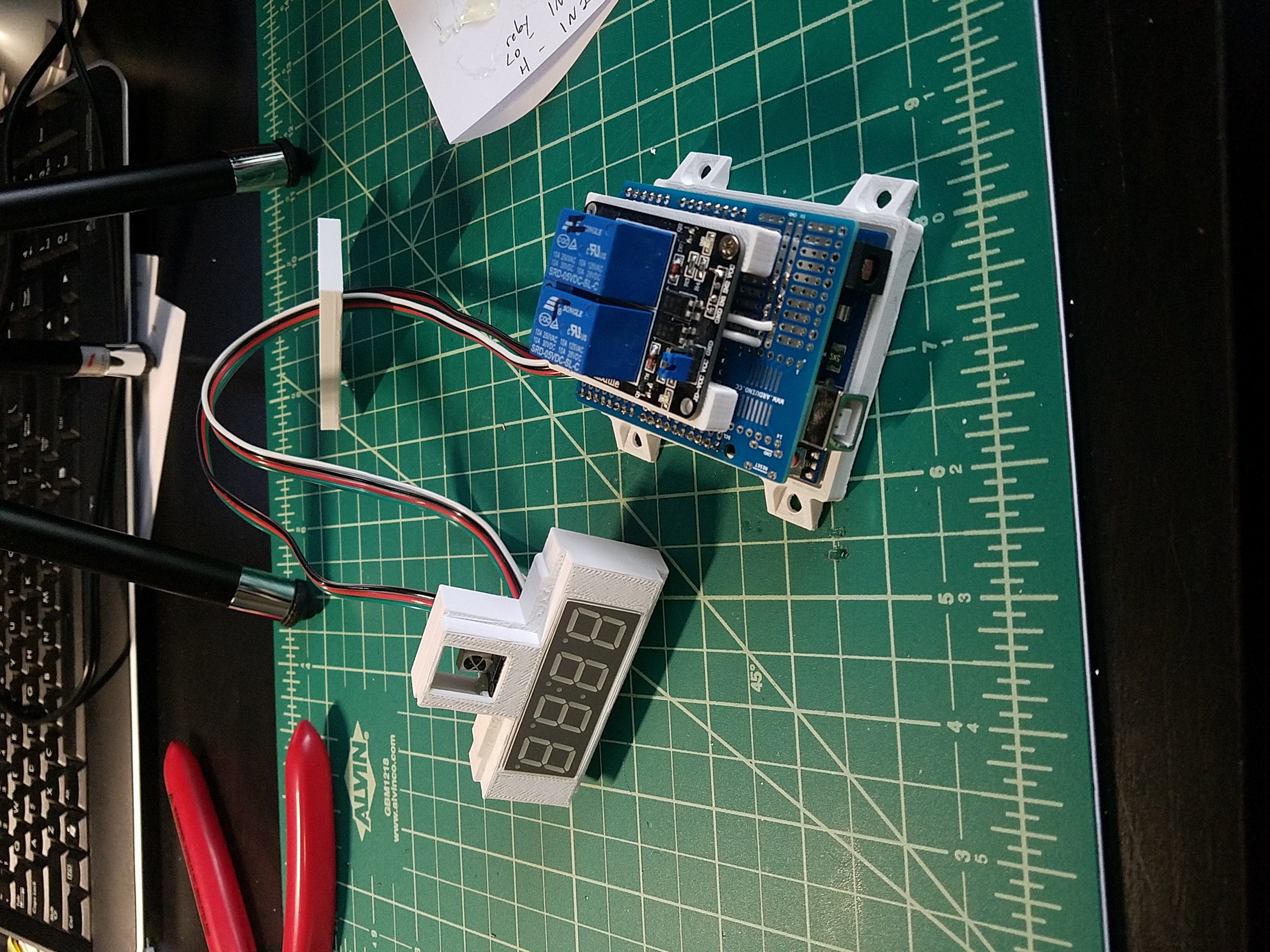
I designed and 3D printed a case and mounting parts for the assembled electronics. The design files are all shared on my thingiverse account. Here is a picture of the finished mounts:
Building the enclosure:
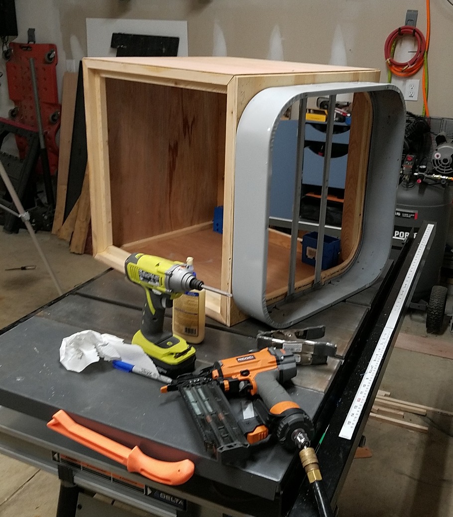
With the electronics complete, it was time to build the ceiling-mounted box that would hold the fan, filters, and electronics. I used a common 20" box fan and two 20x20x1 furnace filters for this project. The sizes of those three parts dictated the size of the case. I worked up a crude layout in sketchup, and then built the whole thing out of scrap wood from past projects. The whole construction process is documented in the video series on Youtube. Here is a shot of the case mostly complete:
Here it is finished, painted, and with the electronics installed:
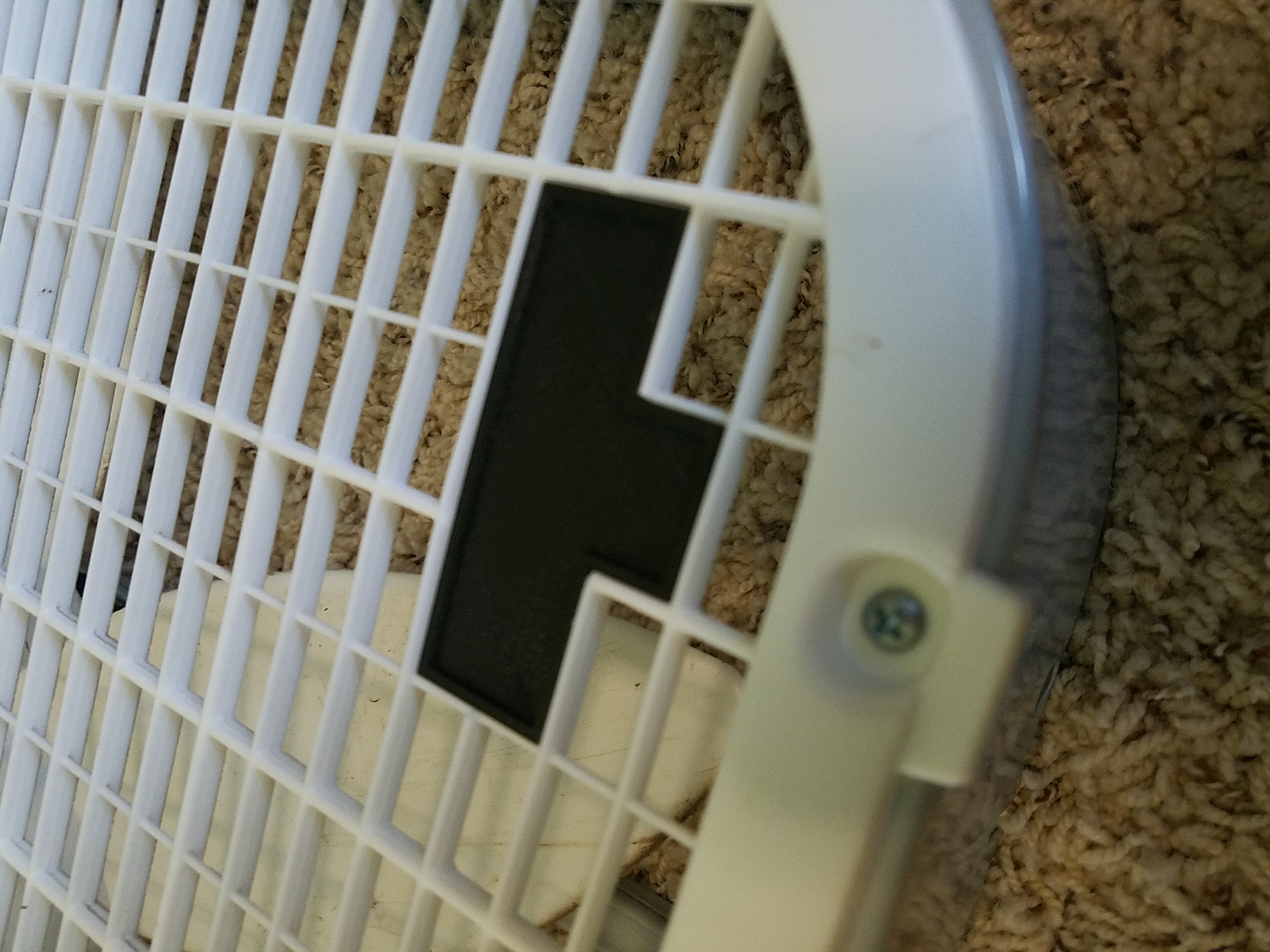
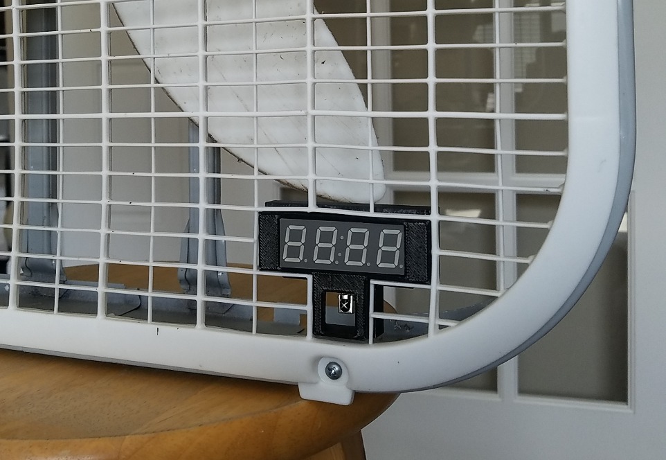
The case for the display and IR receiver was designed to fit perfectly into the fan grill where I had cut out a few grill bars. Here is a close-up of one of the early trial designs:
Here is another shot of the fitment trial and error process of design. I had the design pretty close, but it was still off a bit.
I made a few final corrections to that version and then printed it in white ABS so it would match the fan grill. After that it was ready for installation.
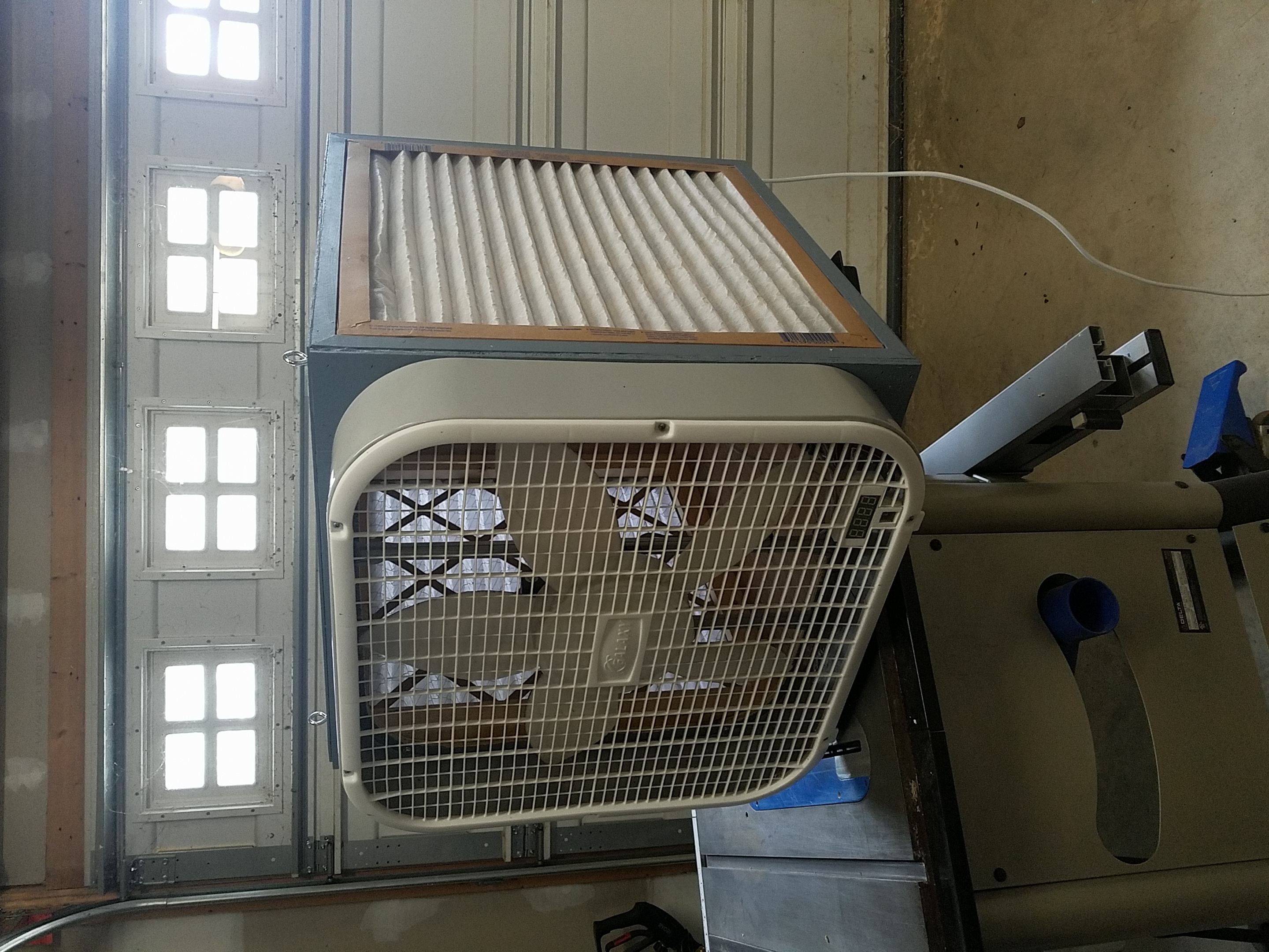
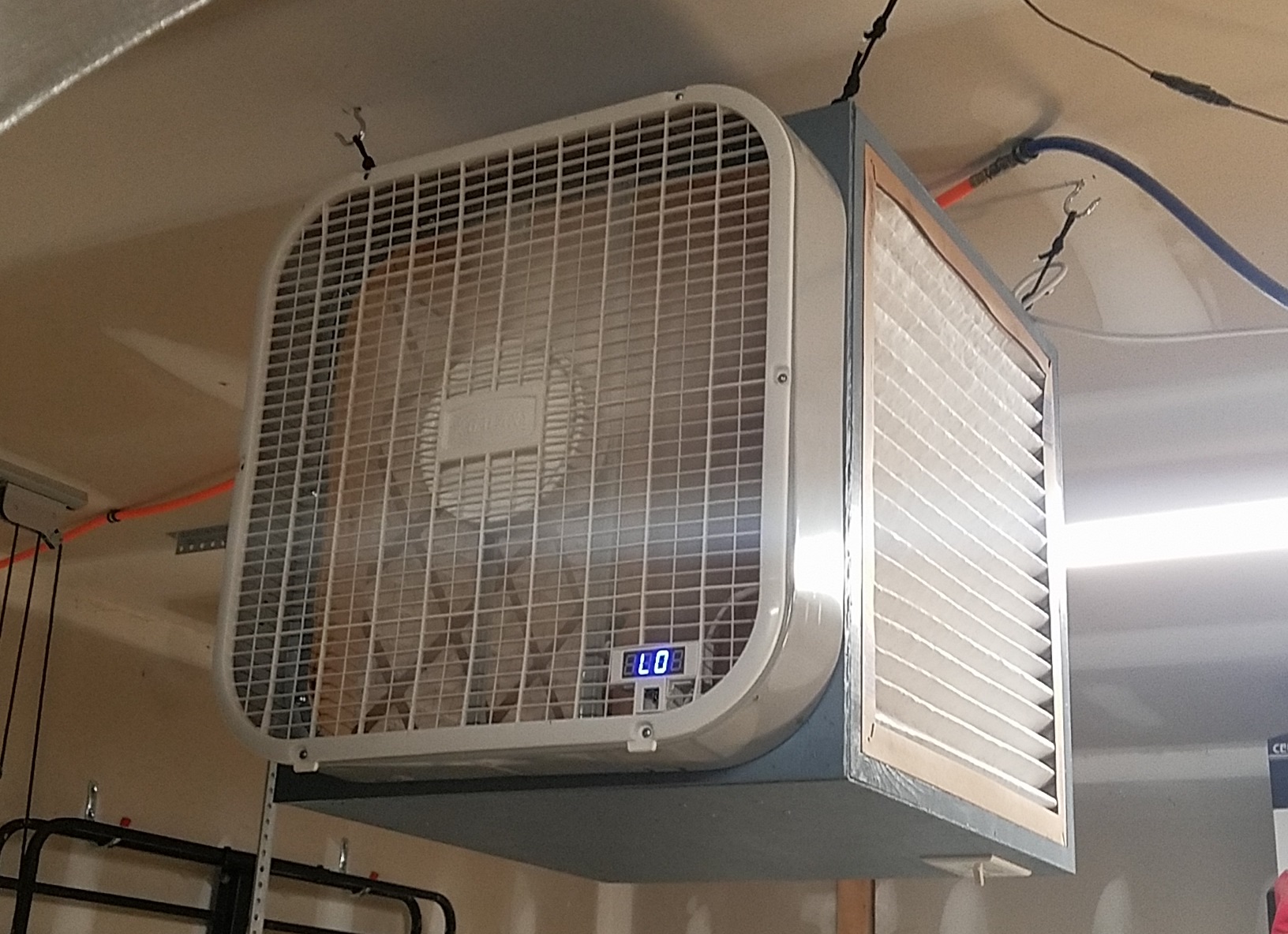
Here is a shot of the final product hanging in my garage.
It works perfectly. I am extremely happy with the results. This was a learning experience for me as I integrated some unfamiliar components and functions into my Arduino code. I have shared all of the code publicly on my GitHub page. You can find the project here.
“We are a participant in the Amazon Services LLC Associates Program, an affiliate advertising program designed to provide a means for us to earn fees by linking to Amazon.com and affiliated sites.”
